The Universal Topological Layer
Description
BREP (Boundary REPresentation) modeling is based on the fact that any solid body divides the R³ space into two continuous sets of points separated by the boundary. Thus, the basic principles of a BREP model is to model the boundary of an object which is, by definition, made out of surfaces. However, a BREP model is much more than a surface model. A surface model only defines an object's boundary as a set of surfaces whereas a BREP solid model also defines relations between adjacent surfaces. Thus, the information inside a BREP model is geometrical as well as topological (the way adjacent surfaces are linked to form edges, the way edges bound surfaces to form faces, …). In fact, a BREP model describes the boundaries as a set of related and oriented faces. Each face is made up of a surface (entity describing the face's geometry) and is limited by a set of edge loops. The validity of this description of a solid object is ensured by links established between all topological entities. Indeed, there is no redundancy in the data structure. The great interest of this type of model, in addition to the insurance of the model's validity is the possibility of knowing locally where is the inside and the outside of the solid, thanks to the orientation of faces. Geometric entities within a BREP model are the same as those present in a wire-frame or surface model. A BREP model is close to be a perfect model as it is unique, non-ambiguous and concise. Space adressability with a BREP model is not straightforward but can be computed quite efficiently. The amount of information that is directly usable in a BREP model for various needs makes it a basic representation used in most of commercial CAD/CAM platforms.
 42,9 Ko
 Practically speaking in the old model, the meshers are well integrated into format SAT. The problem lies in the fact that, although theoretically operation with another modeller is possible, the total reprogramming of the meshers is necessary. The reason is the difference in description of topology between each BREP. Although relatively weak, these differences can significantly affect the writing of a meshers.
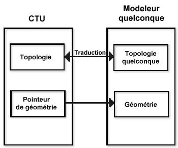
To define a universal topological layer makes it possible not to modify or rebuild completely the applications or elements using this topology, like the meshers for example. The interface allows not only the translation between common syntax , and the one specific to the geometrical engine, but also all the modifications necessary so that the specific topological engine corresponds to the chosen "standard" , the standard ISO 10303. Ideally, these modifications are minimal. The CTU is composed first of all of a geometry pointer which points on an already existing geometry, and of a specific topology which is the translation of witch already existing. Topology includes two types of elements:
- single topological elements
- "cotopologic" elements. They describe, when they are referred by another topological entity the orientation of a face, an edge or a top. The same topological element can be associated one or more "cotopologic" elements.
Formation de la CTU  16,2 Ko |
Modèle BREP utilisé dans MAGiC  12,5 Ko |