Automatic multidimensionnal mesh generation for FEA
Description
When conducting a finite element analysis, the total number of degrees of freedom can be dramatically decreased using finite elements such as beams and shells. Because of geometric complexities, entire models (or portions of models) must be meshed using volume elements in order to obtain accurate simulation results. If however some parts of these models fit the description of shells or beams, then a mixed dimensional model containing shell, beam and volume elements side by side can be used. This approach, referred to as mixed-dimensional analysis (MDA) can significantly reduce the time needed to mesh and solve the system.
Figure 1: A 3D model and an equivalent multidimensionnal model
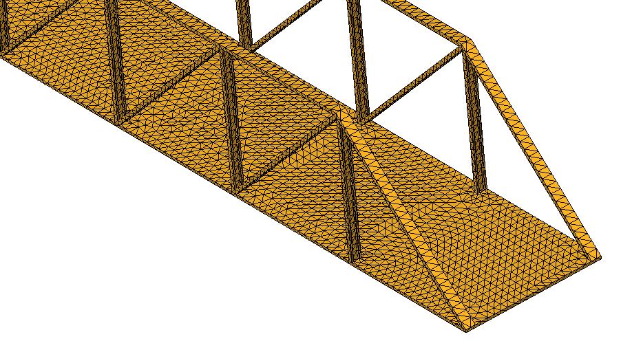
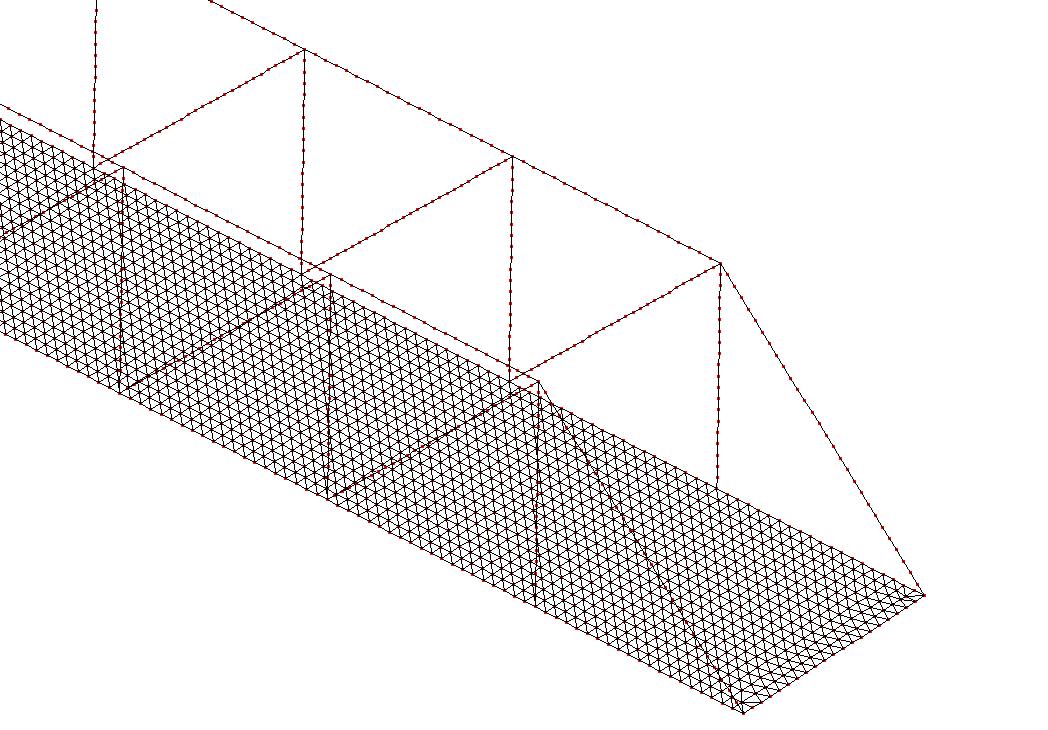
Unfortunately, problems arise when trying to connect different types of elements in part due to incompatibilities between degrees of freedom, and due to discontinuities between meshes generated independently. This paper presents a solution to these problems based on the generation of a compatible mesh composed solely of standard finite elements and without requiring the use of constraint equations. This mesh can then be exported to a standard FE solver without using specific connexion elements.
The process is based on automatic face splitting and connexion beams referred to as mini-beams to induce a rigid connexion with the actual shape of the connexion zone (the beam section for a beam-solid connexion).
Figure 2: Basic principles: face splitting and using mini-beams inducing a rigid connexion
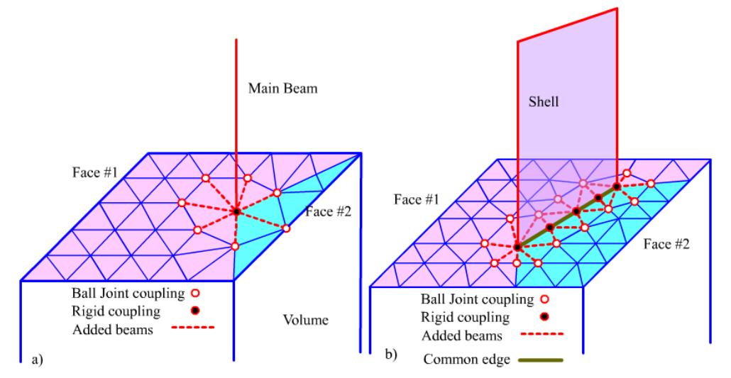
Figure 3: Face splitting and mini-beams for a beam-solid connexion
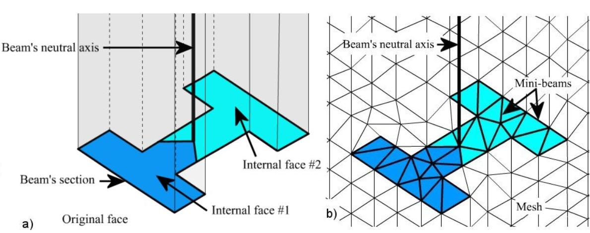
Figure 4: Face splitting and mini-beams for a shell-solid connexion
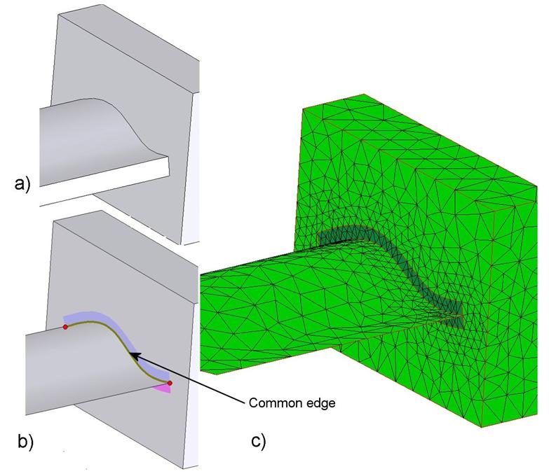
Figure 6: Stress distribution for a beam-solid connexion
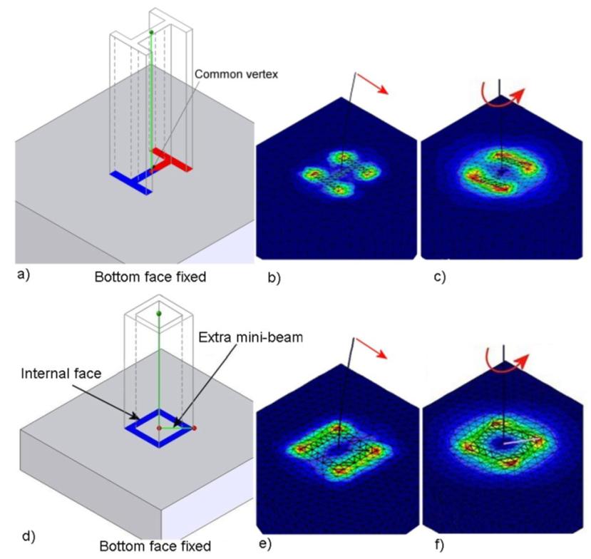
Figure 7: Stress distribution for a shell-solid connexion

We made many validation tests to compare our approach with other alternatives. The tests consist in connecting beams and shells with a volume and comparing the stress results with a reference model, which is meshed using 3D quadratic elements and which is extremely refined. Stress results along evaluation lines, obtained from different FE models are plotted to make comparisons between these FE models.
The two following figures illustrate sample validation tests obtained for a connexion between a square beam and a volume and a connexion between a plate and a volume.
Figure 8: Validation results for a beam-solid connexion
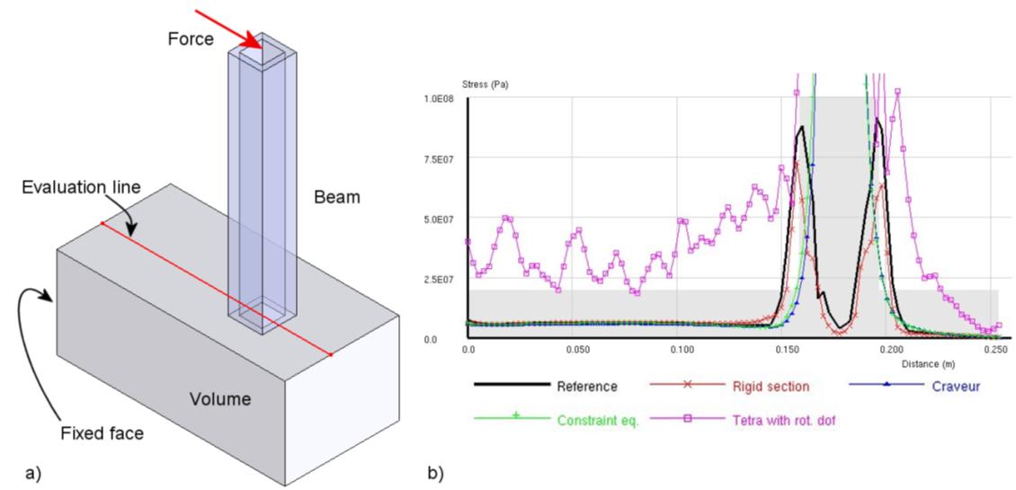
Figure 9: Validation results for a shell-solid connexion
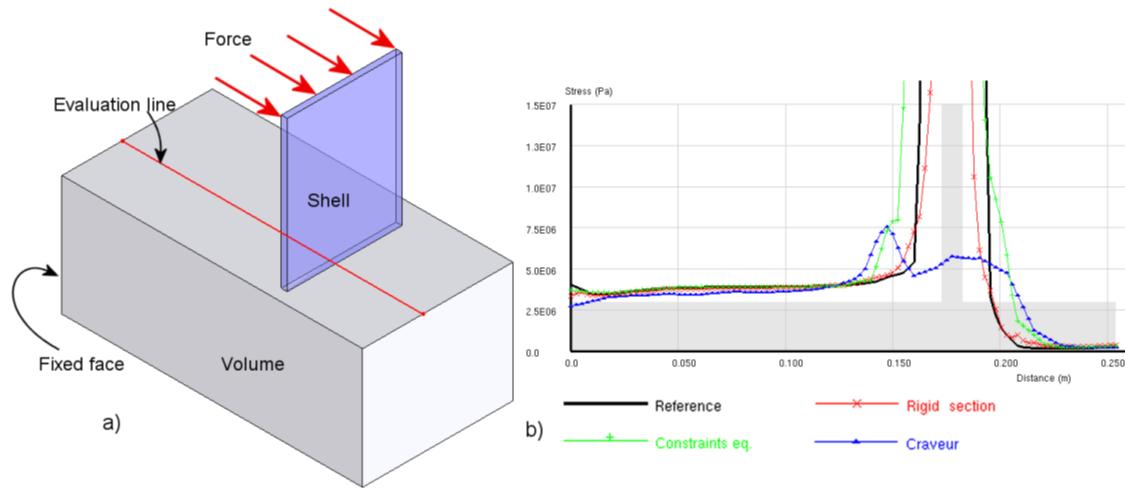
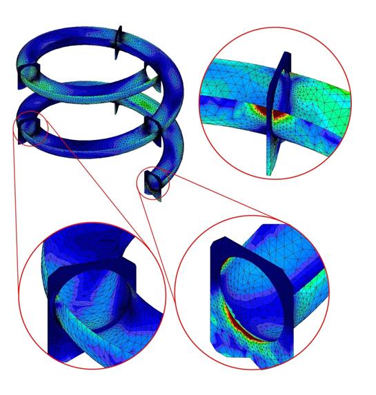
Figure 10: A practical result with beam-solid connexions
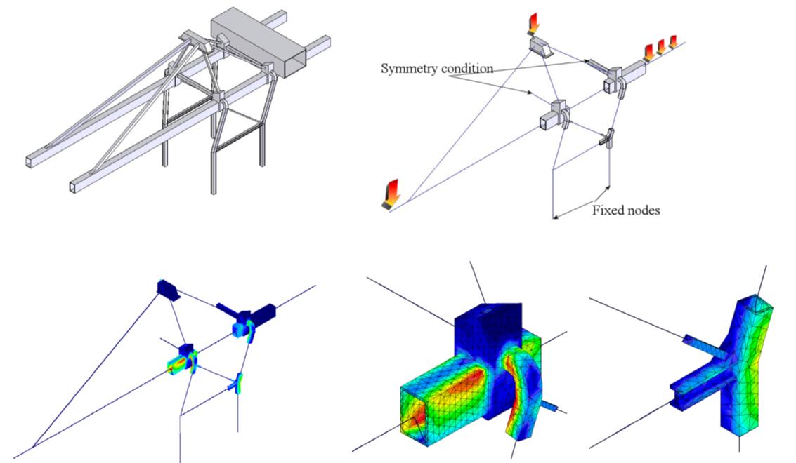
Figure 11: A practical result with shell-solid connexions
