Automatic Remeshing
Description
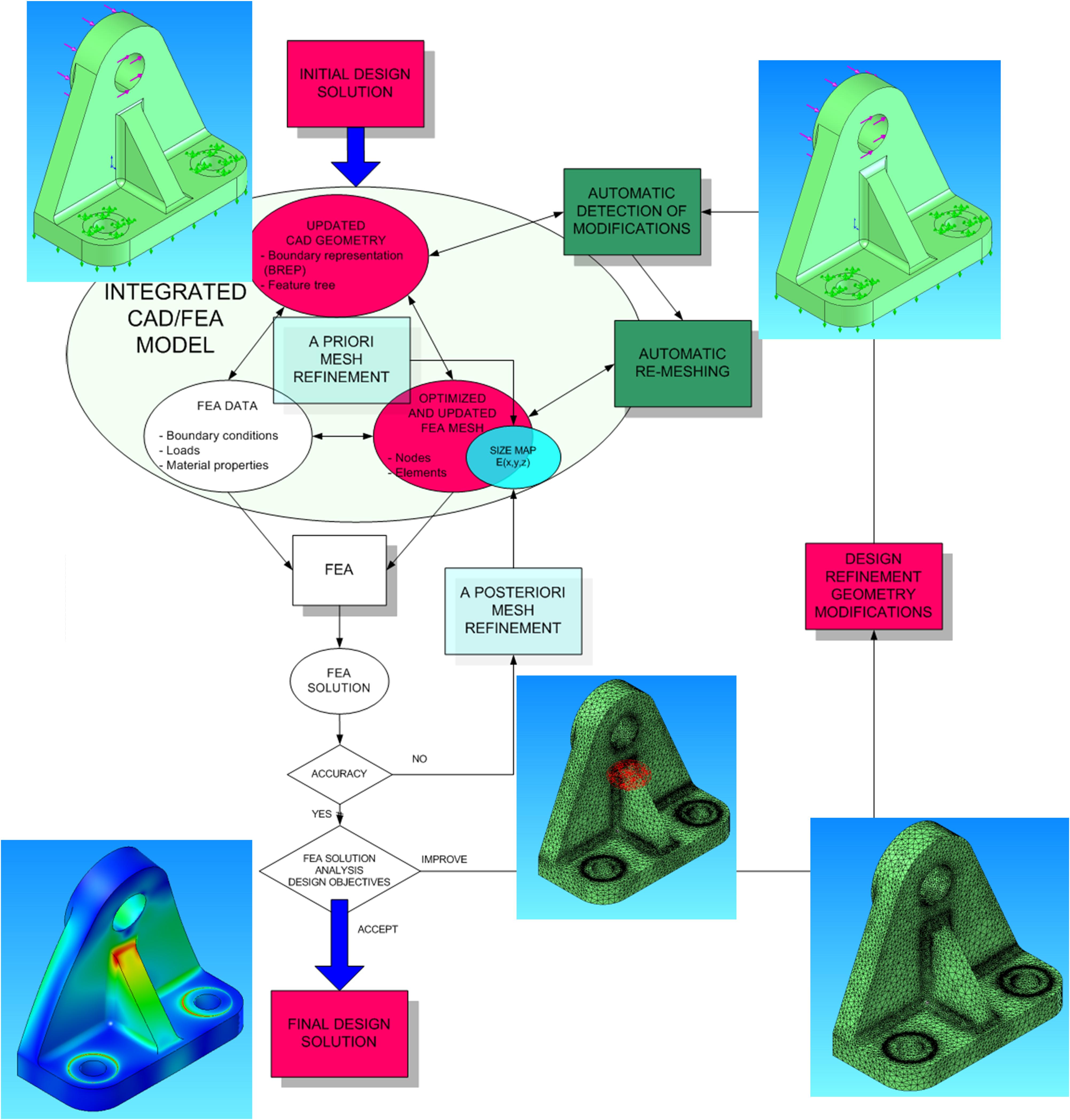
The process of designing parts, structures and assemblies is subjected to an ongoing transformation with the use and development of CAD/CAM/CAE technologies. One of the major benefits in using these technologies is being able to easily access and eventually reuse engineering data from previous design projects or from previous steps of a given design project. The design process is indeed a dynamic process during which an initial geometry, more generally an initial design solution, is gradually modified an optimized to obtain a more or less final design solution that fulfills design constraints and requirements.
We introduced the automatic remeshing concept, which basically consist of automatically retrieving mesh elements between two subsequent versions of a part. This process has proved to be extremely powerful, especially when modifications are limited and spatially confined.
Figure 1: Automatic remeshing through the design process
Automatic remeshing 1 : Geometric modifications only
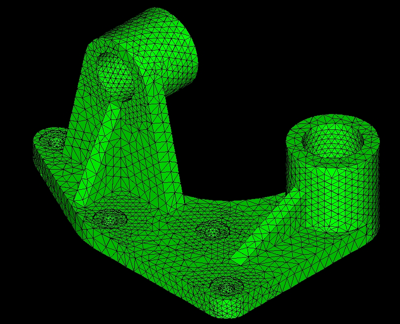
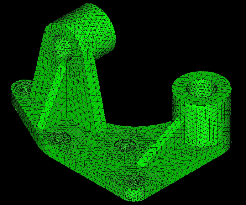
This strategy applies when the initial part is modified without changing its topological structure. As an example, this type of modification frequently occurs when modifying dimensions in a parametric solid modeler. The basic principle applied here is to keep the same number of nodes and triangles and the same mesh topology. Thus, the initial mesh is directly fitted to the new geometry by a set of changes in the nodal positons.
The gains in CPU time obtained with this approach are particularly spectacular since the remeshing of usual mechanical parts is carried out in a few seconds (12 seconds for the first sample part below featuring 27000 tetrahedrons)
Figure 2: Automatic remeshing of a lever (the diameters of two holes have been reduced)
Automatic remeshing 2 : Geometric and/or topologic modifications
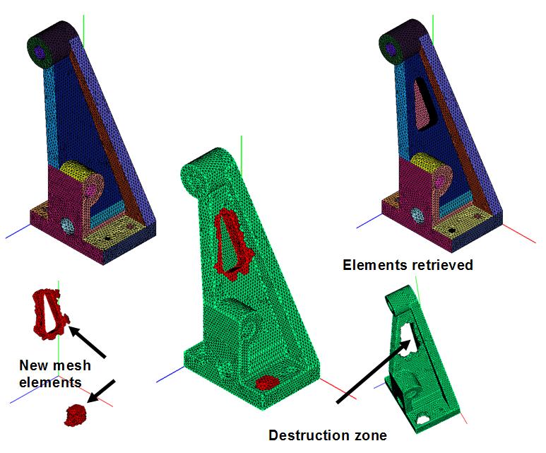
This strategy applies for any type of modification in the initial part's geometry and/or topology. The basic idea is to keep as many tetrahedrons as possible from the initial mesh destroying the initial mesh in modification zones. Consequently, changes between the initial and modified parts have first to be detected. This is made using an octree based procedure where cells of the octree structure are associated with modification zones. After this tetraedrons are destroyed around these cells. The process ends with the automatic generation of tetraedrons in zones where elements have been destroyed.
Figure 3: Automatic remeshing of a bracket (an opening has been added in the stiffener)
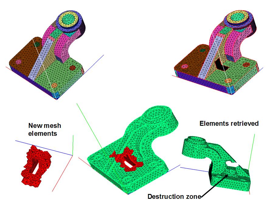
Figure 4: Automatic remeshing of an an ejector base (a pocket has been added and a hole moved)
