CAD Model Simplifications for FEA
Description
Vision & concepts : Adapting CAD models for simulation needs using form features and virtual topology, composite-surface meshing.
Some fundamentals questions :
Does my CAD model allow mesh generators to respect the optimal finite element sizes ?
What kind of details can be removed using the form features of my CAD model ?
How can I improve mesh generation by merging faces of my CAD model ?
How should one integrate CAD and simulation ?
Description:
Thanks to its integration inside computer aided design (CAD), finite element analysis (FEA) tends to be used to optimize products in the early design stage. This integration requires the adaptation of the geometric model designed inside the CAD system to fit the FEA needs.
Nowadays, this preparation of the CAD model for FE simulation remains a complex task, and represents an important part of the time required in the simulation work. The causes of this complexity come from the three folowing levels :
- the CAD models often contain form features which are removable compared to the simulation needs, but severely complicate the complexity of models' preparation and problem solving,
- the B-Rep model's topology often represent too small faces compared to the expected FE size, which do not have any mechanical meaning,
- the meshing methods often impose the respect of the faces of the B-Rep model.
The objective of this project is to elaborate a method able to automatically identify and perform the required geometrical treatments to adapt the model in preview of the FE simulation. The proposed approach is based on three different levels of operators :
- elimination of features when they don't influence the mecanical behaviour. We preview to use form feature desactivation and delete faces operators to perform this treatment level.
- simplification of the B-Rep's faces by virtual topology operators,
- automatic meshing using the virtual boundaries of the B-Rep's virtual topology.
A shape feature removal approach for CAD models
While many works focused on feature-based design and feature recognition, very few criteria were proposed to identify features that should be removed to simplify FEA models : bosses, fillets, holes, (...) that are “small” when compared to the specified mesh size.
Our criteria identify details that are irrelevant for meshing, by comparing dimensional parameters of shape features with the size of FE elements that should discretize them (conforming with the specified size map). By definition of a h-adapted size map, removing these details will have a negligible impact regarding the simulation accuracy goal. Hence, these geometric criteria translate the mechanical behaviour of the physical system.
The second aim of these criteria is the identification of CAD operations to remove shape details :
- the delete-face operator, available in current CAD software, is used to simplify partially hole details,
- fillet and chamfer features are simplified locally by editing the edge list on which they are applied,
- other features are eliminated by suppressing them in the feature-tree of the part : extrusion cuts and bosses, fasteners, etc.
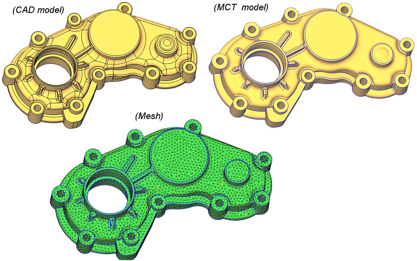
Figure 1: Our three steps simplification process
Figure 2: The result of our three steps simplification process

Figure 3: Step 1, CAD feature removal from the feature tree

A topological model for the representation of meshing constraints in the context of FEA
The preparation of a Finite Element Analysis (FEA) model from a computer aided design (CAD) model is still a difficult task since its boundary representation (BREP) is often composed of a large number of faces, some of which may be narrow or feature short edges that are smaller than the desired FE size (for mesh generation). Consequently, these faces and edges are considered as geometric artefacts that are irrelevant for the meshing process. Such inconsistencies often cause either poorly-shaped elements or meshes that are locally over-densified. These inconsistencies not only slow down the solver (using too many elements) but also produce poor or inappropriate simulation results.
Virtual Topology approaches (Sheffer, 2001; Inoue et al., 1999) aim at clustering faces of the BREP definition of a CAD model to produce a new topology more suited to meshing constraints.
A major issue still to be addressed is the lack of topological data-structure and operators general enough for the generation of FEA-models. Indeed, Euler operators and BREP topology used in previous works do not enable the representation of edges and vertices isolated inside the domain of faces, while these topological configurations are often required to represent interior boundary conditions, highly stressed features, and sharp shape features.
Criteria that should be used in order to automate the topology simplification process, constitute another interesting and crucial issue on this subject. For example, in (Sheffer, 2001; Inoue et al., 1999) the face clustering process is based on global properties of entities (face area over edge length ratio, maximal curvature along an edge), while geometric properties may vary along entities (for instance a face can be narrow only locally). As a result, this type of face clustering process denies the identification of narrow regions in faces. Lee and al propose in (Lee et al., 2003b) a criterion based on the medial axis transform (MAT) aiming at the identification of narrow regions in faces, but no criterion is proposed to take into account the local curvature of surfaces.
To propose a topological model well suited for FEA, we proposed the Meshing Constraints Topology (MCT) aiming at transforming a CAD model in a FEA model featuring only faces, edges, and vertices that are relevant for meshing. Therefore, MCT models represent explicitly the topology of meshing constraints entities.
Three face-edge-vertex adjacency hypergraphs represent the MCT topology, and simple graph operations define MCT adaptation operators.
It's worth noting that the edge deletion operator is not an operator from the Euler's group, then enabling the creation of edges and vertices isolated inside the domain of faces (non-manifold configurations).
Topological orientation information (co-faces, co-edges...) are inferred from the orientation information of underlying MCT composite curves and surfaces.
At the end of the MCT adaptation process, the hypergraph-based topology can be converted in a non-manifold BREP topology, to enable processes such as advancing front triangulation.
Adaptation criteria aim at identifying MCT operations needed to transform a CAD model boundary decomposition into a FEA model, featuring only meshrelevant faces, edges and vertices, i.e., an explicit data model that is intrinsically adapted to the meshing process. These adaptation criteria take into account meshing requirements as following :
- size map conformance : the distance between face boundaries is analyzed locally in order to identify edge partitions that should be suppressed. The length of edges is also analyzed to identify vertices that should be removed.
- discretization accuracy : the discrete curvature across edges is analyzed locally in order to identify sharp corners. Indeed, sharp corners must be represented by edges and vertices in order to generate an accurate mesh,
- discretization of the boundary conditions domains : boundary conditions domains must be represented by topological entities in order to constrain the mesh to correspond to it, e.g., a point on the part where forces or displacements are applied must be represented by a coinciding node, a set of faces where pressure is applied must be discretized with a set of elements entirely inside the corresponding area, etc.
Figure 4: Step 2 , The MCT

Figure 5: MCT operators

Topological entities are removed by MCT operators when the distance between face boundaries is too small to respect the size map or when they are not required to respect the discretization accuracy and boundary condition domains.
A trans-patch extension of the advancing front method for composite geometry meshing
Our latest contribution extends the advancing front triangulation over parametric surfaces (Cuillière, 1998) to surfaces composed with multiple parametric surfaces, and its main features are :
- elements are generated directly over multiple parametric surfaces : advancing front propagation is adapted through the extension to composite geometry of propagation direction, propagation length, and target point concepts,
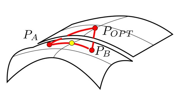
- each mesh entity is associated with sets of images in each reference entity of the composite geometry. Images are generated using the same transpatch path generation procedures, or by the calculation of the shortest path through routing points,
- the intersection tests between segments are performed in the parametric domain of their images.
Figure 6: Step 3, Generating triangles over composite geometry

This method is new and promising for the following reasons :
- unlike previous re-parameterization based schemes, the proposed method has no limitations concerning the type and topology of composite surfaces involved,
- images lying on the exact geometry facilitates adaptive refinement (h or p methods).
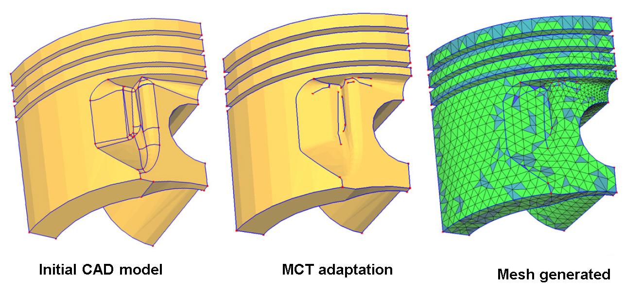
Figure 7: Result obtained on a piston

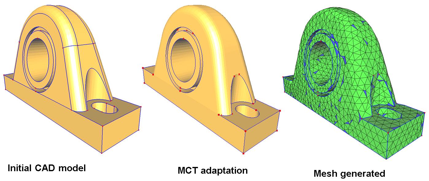
Figure 8: Result obtained on a bearing

