Automatic Comparison between CAD Models
Description
Automatically detecting modifications between CAD models has many potential applications in product development processes. Tracing modifications throughout the design and manufacturing cycle of a new product, based on CAD/CAM/CAE tools, is one of these applications. Easily retrieving and reusing existing designs, along with engineering data associated, is another very interesting perspective. Such an automatic identification of differences between CAD models is of great practical interest for many applications and making it invariant to affine transformations is a major issue and as well as a very complex problem. We proposed new shape descriptors that are focused on this invariance. These descriptors use vector-based representations of geometry, which can be successfully applied for accurate, local and automatic comparisons between CAD models.
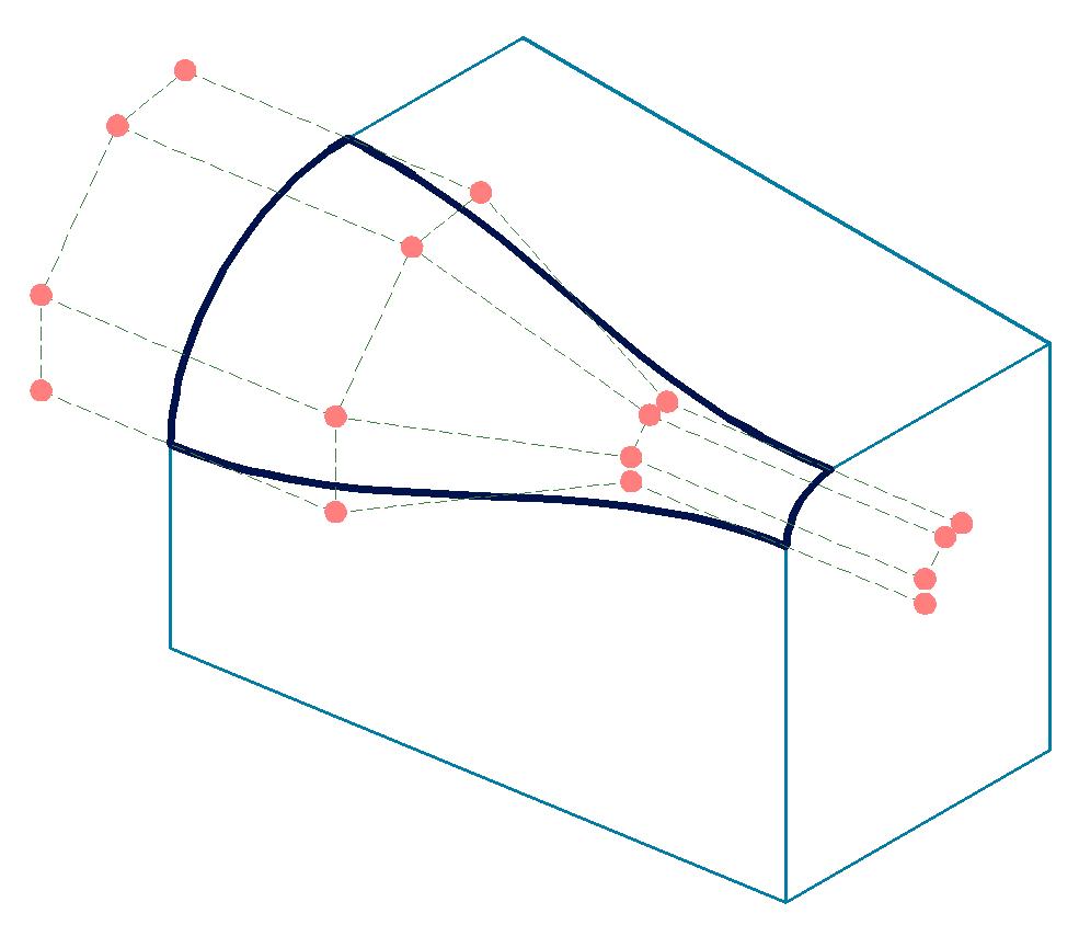
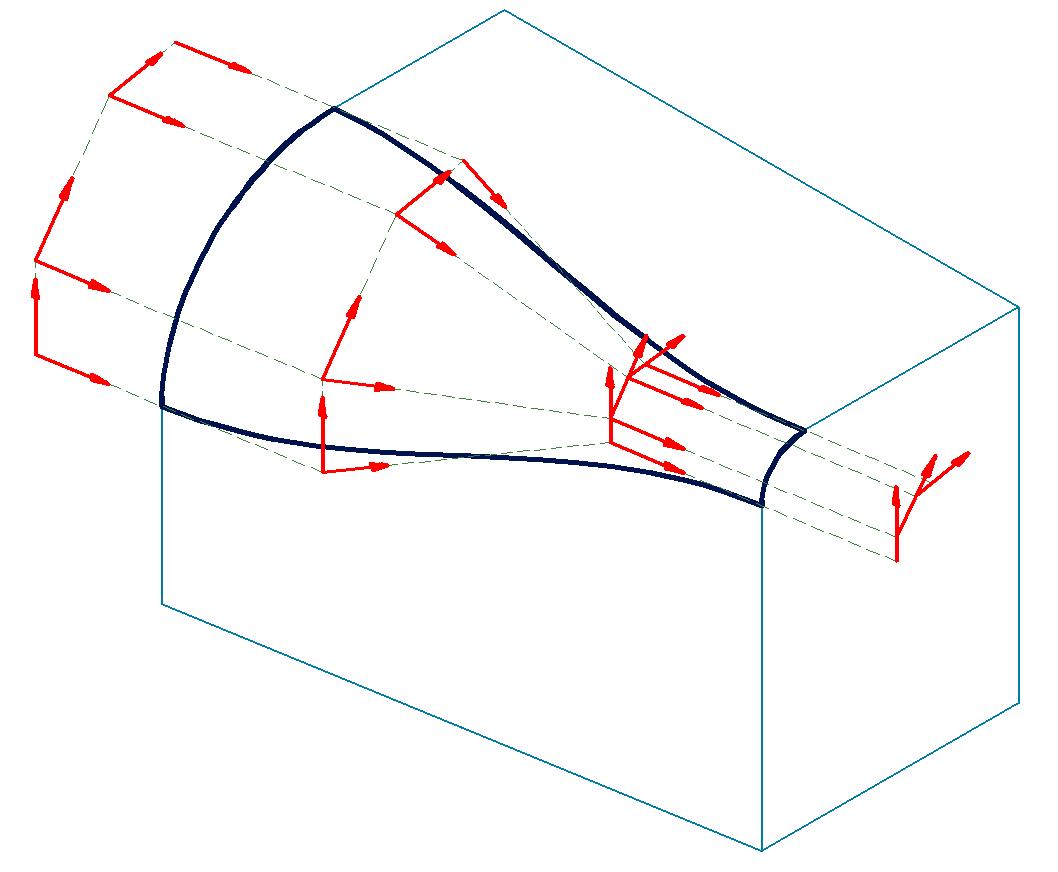
This vector-based representation, referred to in our work as the vectorial space, is automatically derived from a BREP, without requiring any additional information of any kind. It is synthesized as a set of tensors, which are then used to make comparisons between models. These tensors are computed from the control points of Non-Uniform Rational B-Splines (NURBS) representations of CAD model's faces and edges. These points are derived into vectors, tensors and frames (metric and inertia tensors, barycentric frames).
Figure 1: NURBS control points derived into vectors
Results obtained demonstrate that this vector-based representation of geometry can contribute, possibly in conjunction with other shape descriptors, to setting up powerful and efficient CAD models comparison tools. One of the major challenges induced by invariance to affine transformations is finding the best pair of candidate reference faces. A candidate reference face in one of the two models under comparison is a face that has an identical face (same type, same topology and same dimensions) in the other CAD model. Figure 2 and Figure 3 illustrate comparison results obtained from two different pairs of reference faces.
Figure 2: A first pair of reference faces
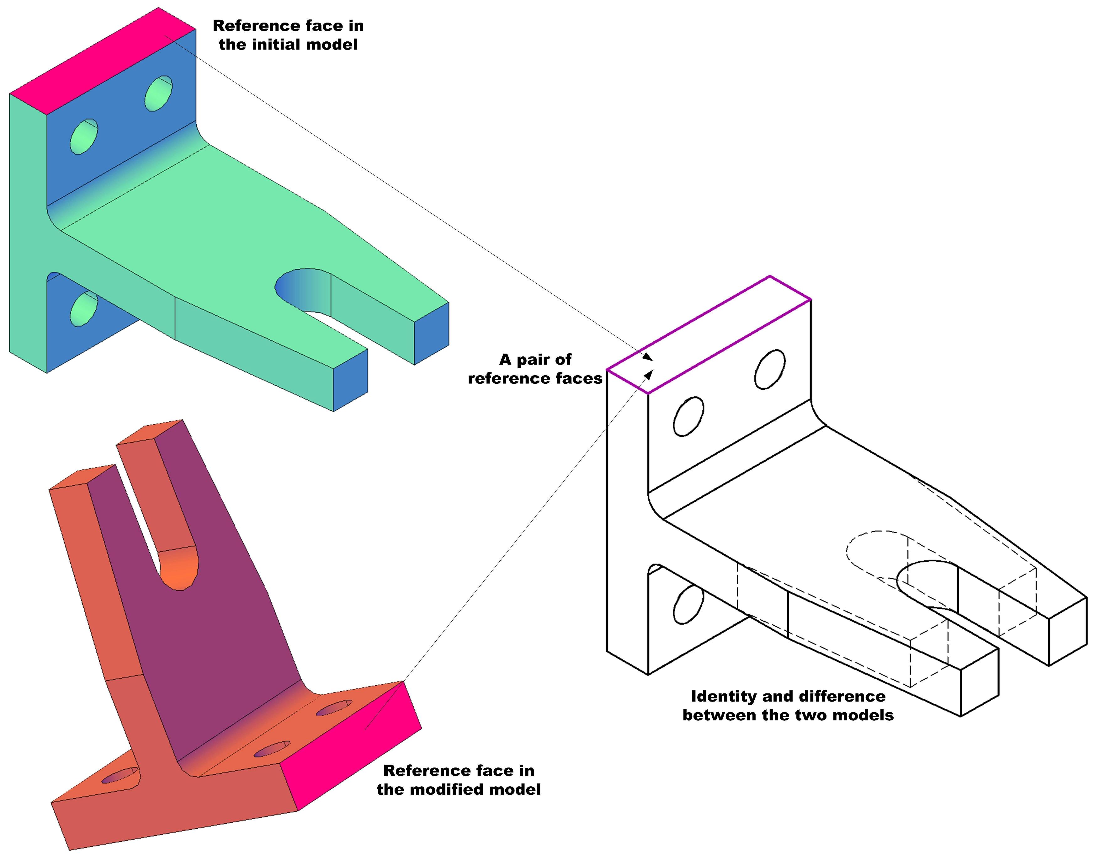
Figure 3: A second pair of reference faces
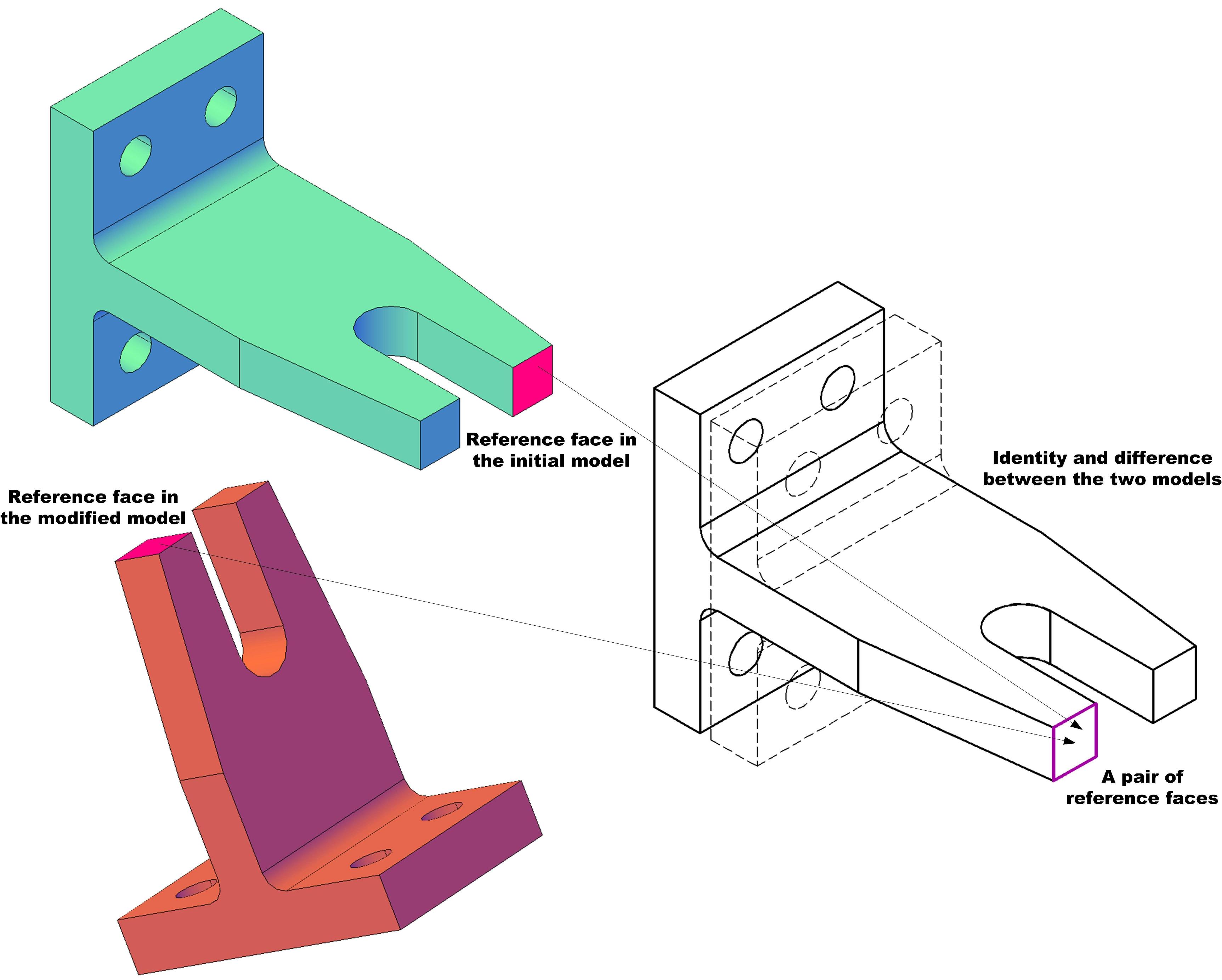
Identity or difference between the two models is obviously directly related to the pair of reference faces considered. For real life CAD models, the number of combinations between candidate reference faces can be huge and, due to symmetry, some of these combinations are equivalent (this is the case in this example). Automatically identifying reference faces and automatically choosing the best pair of reference faces underlies our approach and represents one of its most important advantages.
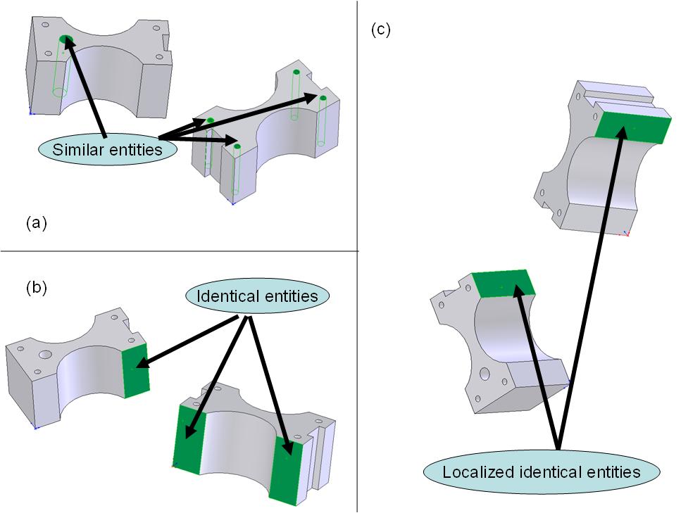
The comparison between models considers the following terminology (Figure 4) when comparing BREP entities from two BREP models (typically when making comparisons between BREP edges and faces). The two BREP models under comparison are referred to as the initial and modified BREP models and they are compared using the following three categories: similar, identical, and localized identical. Two entities are similar if they have the same shape regardless of their size. Two entities are identical if they are similar and if their dimensions are the same. Two entities are identically localized if they are identical and if their location is the same relative to the same reference face in both models.
Figure 4: Similarity, identity and localisation
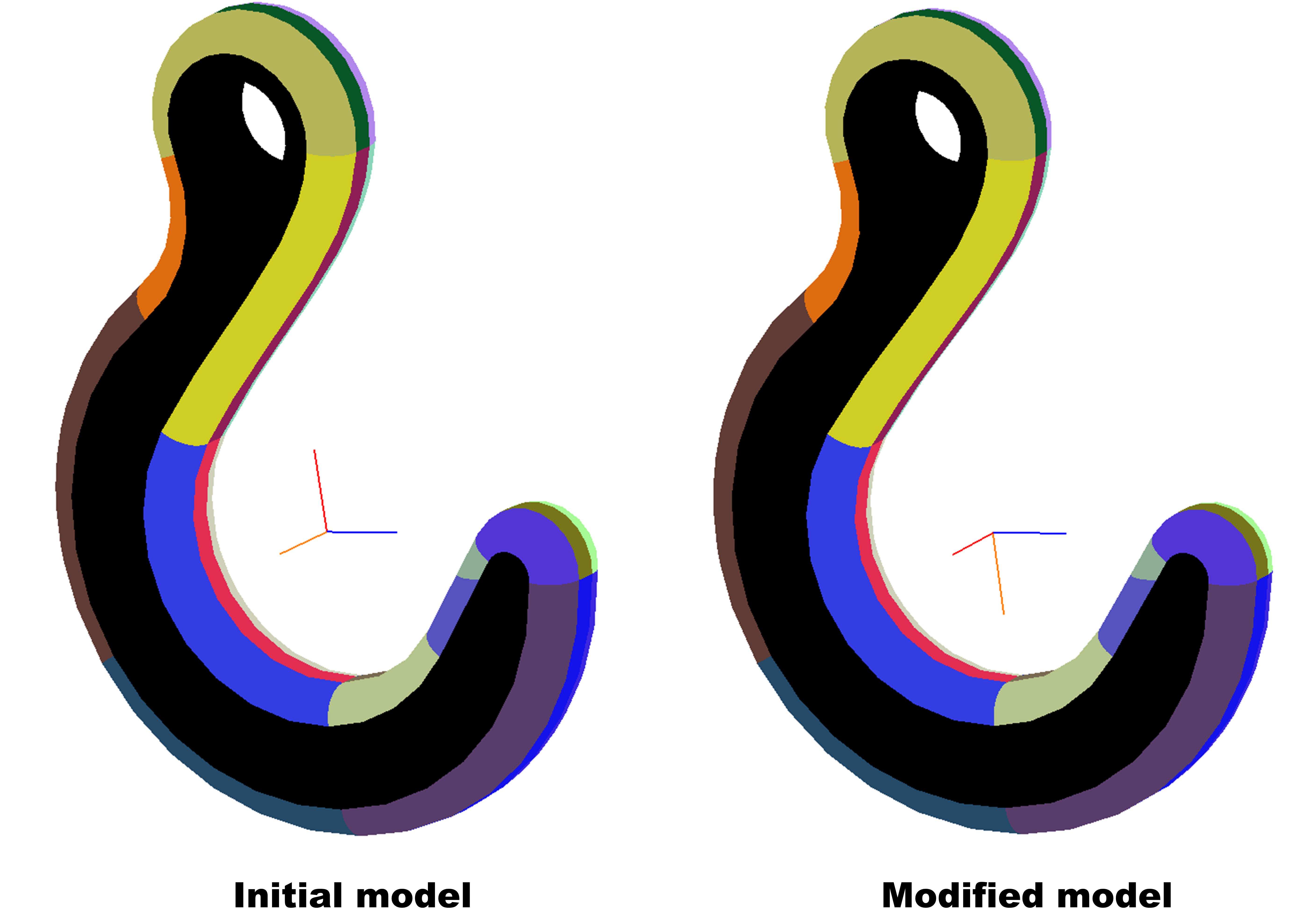
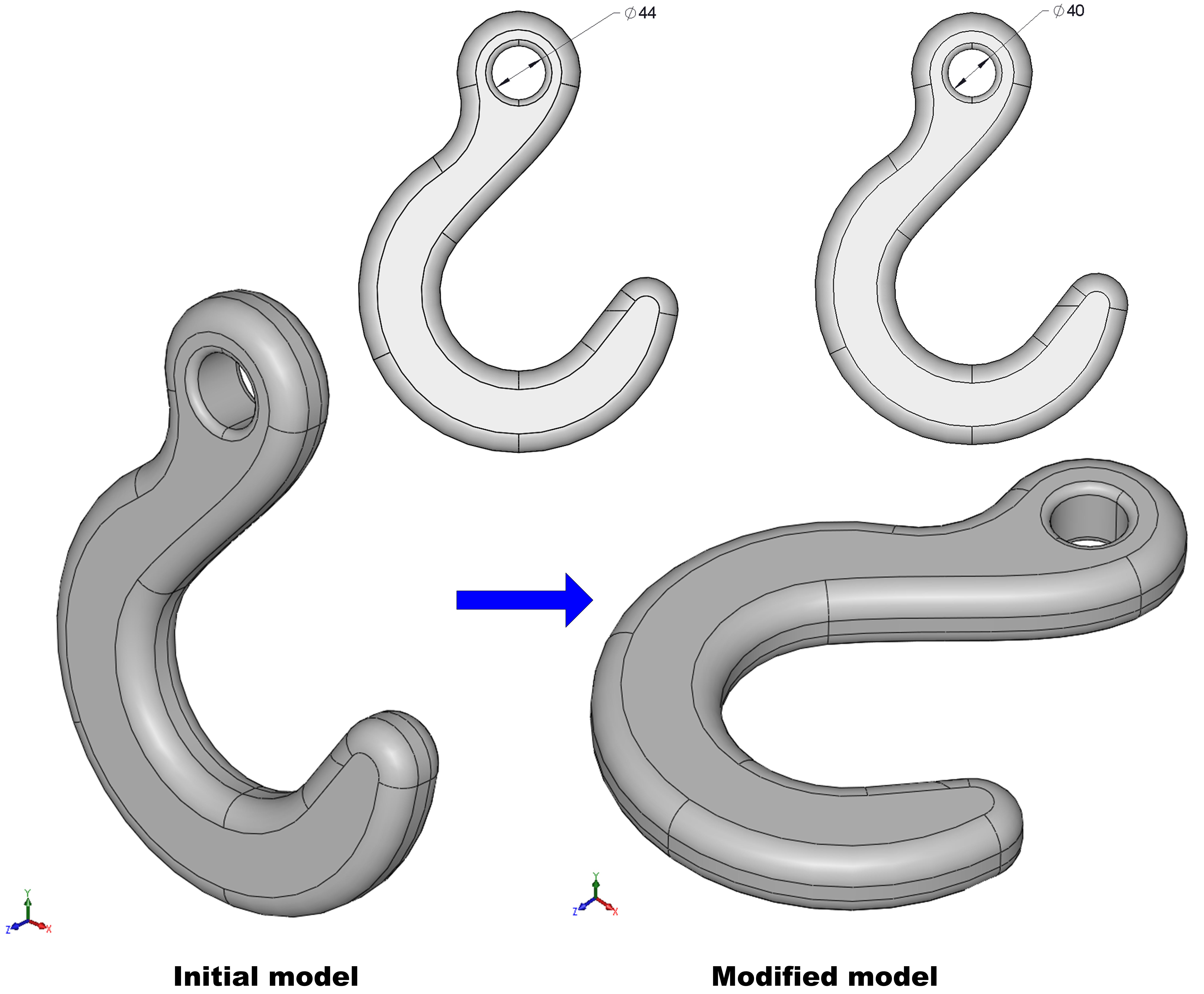
A result is presented below on a hook for which the hole diameter has been modified and the orientation changed (Figure 5). In Figure 6 entities identified as localized identical are represented using the same colour and entities identified as modified are black.
Figure 5: The initial and modified CAD models of the hook
 :
:
Figure 6: Comparison results
