Injection molding simulations
Description
Mesh generation methods
The re-meshing methods presented here are based on the Delaunay criterion for simplicial triangulations. An extension to discrete curved surfaces is proposed. This extension allows one to get rid of the link with the exact CAD model of the surface. We use instead an approximated tessellated surface to represent the geometry. In fact, the possibility to generate anisotropic surface meshes without link to the CAD allows for an easy interface with finite element codes. We developed a C++ kernel able to produce an anisotropic mesh that is adapted in density, also capable to take a simple geometrical representation of the domain of interest as an input. This work is part of two journal publications.


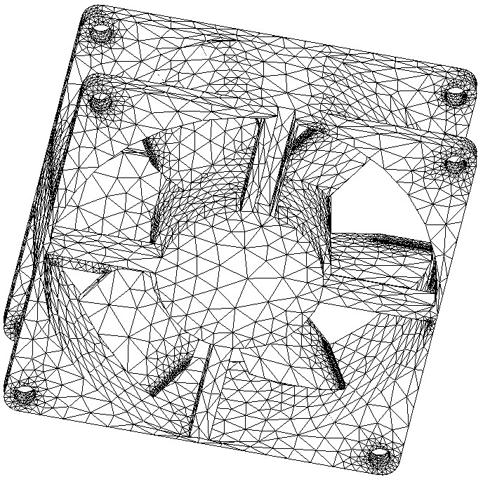
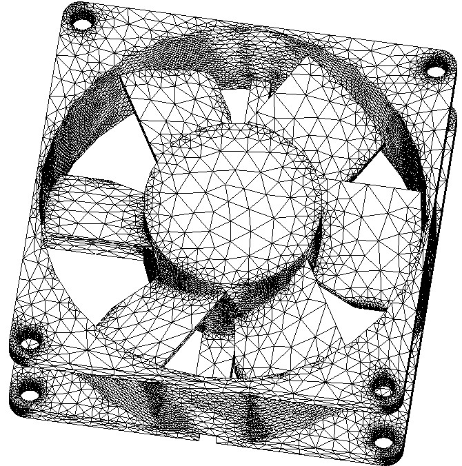
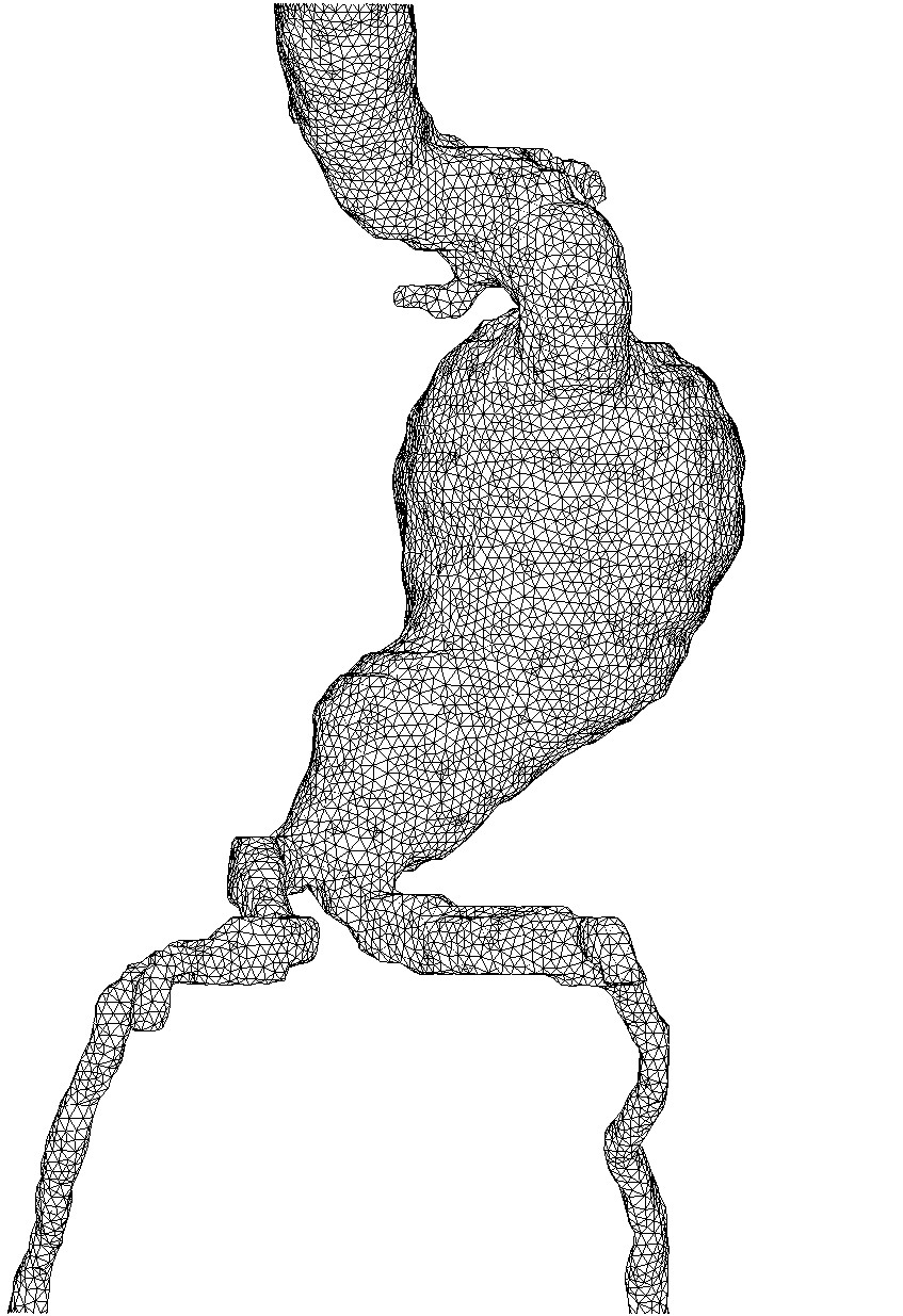
Re-meshing examples : from an STL file (left); from medical MRI scan (right). From E. Béchet, J.C. Cuillière, F. Trochu, Generation of a finite element mesh from stereo-lithography (STL) files, Computer Aided Design, 2002.
Injection molding simulations (free surface flows)
Many scientific computation procedures depend on mesh generation to obtain quality simulations for various physical problems . The physical problem here is RTM mold filling. This process is similar to thermoplastic injection, though the fluid moves here across a porous media. This porous media is the reinforcement found in classical FRP. The objective here is similar as in thermoplastic molding : to produce quality parts at a reasonable cost. Flow motion behavior is that of porous media, and multi-physics phenomena take place as the flow is usually depending much on temperature, which in return depends on the kinematics via the cure factor of the resin.
Simulation of flows encountered in mold filling depend much on the discretization in the vicinity of the resin front. Classical methods use a fixed mesh and a local filling algorithm based on the volume of fluid (VoF) approaches, with two major drawbacks :
- a high number of time steps to get good results (the time step is directly proportional to the mesh size)
- an excessive diffusion takes place around the front position
These two remarks are the base that lead to the development of an original adaptive re-meshing and filling algorithm. Most of the RTM flow simulations are made on surface models. A 3D model depends on a fine knowledge of transverse permeability measurements for the reinforcement. This knowledge is still in a research state so simulations shown here are exclusively made for surface geometries.


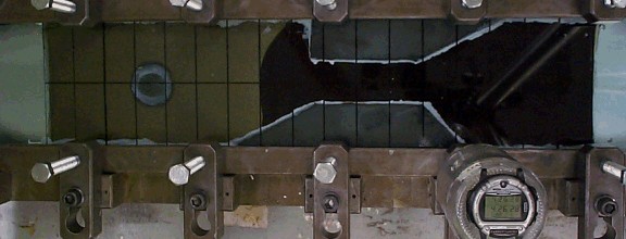
Experience vs. simulation comparison for a case of RTM injection. From E. Béchet, E. Ruiz, F. Trochu, J.C. Cuillière, Remeshing algorithms applied to mould filling simulations, Journal of Reinforced Plastics, 2003.
A filling algorithm has been developed. This is based on the level-set method. This allows for stability conditions on the time step for the flow motion. At the same time, re-meshing is done to keep a good description of the flow front. For this, an anisotropic size map is generated, depending on the local flow velocity. In the isothermal case, the fluid motion law is Darcy's law for porous media. This law has no "history" thus successive re-meshing are easy to implement as no variable switch between meshes occur. Also, there are no numerical stability limits on the time step. An experimental setup has been developed to validate the algorithms.
This part has been published in an international journal.
An extension of this method for non isothermal flows has been done. In the RTM process, thermal phenomena are of many kinds : diffusion/transport in the flow motion, heat exchanges between the resin and fibers (reinforcement) or the mold walls., and heat generated due to the curing of the resin. The proper numerical model of these phenomena implies the projection of some solution field from the current mesh onto a new mesh, as well as transport. The "'history" is important here as thermal aspects are inherently dynamic.
The transport method used here was originally devised by Lesaint and Raviart. That one has time steps restrictions (CFL or Courant-Friedrichs-Lewy). The time step used for thermal simulations is then different from that of the mechanical (flow front update) part. In addition to that extension to thermal phenomena, research has been done to generate an a priori adapted mesh used all along the computation. This mesh is generated with a flow computation made with a totally filled mold. This solution is analyzed via two criteria:
- local error estimator (Zhu-Zienkiewicz)
- local flow velocity
The idea here is to generate a mesh that is optimal with regard to both the interpolation error and the number of layers. The number of layers determines the number of time steps of the simulation. The results of this study have been published in an international journal.
