Automatic 3D mesh generation
Description
A mesh generator transforms a complex 3D body into a set of elementary bodies (called elements) restrained to elementary topology (tetraedra, bricks, …) inside of which shape functions Ni are known.
Automatic mesh generation can be achieved by numerous methods that can be classified between the 4 following groups :
- Manual methods were historically the first methods to be used. he user enters in an interactive way the coordinates of all nodes and the connection of nodes in order to form elements. This process can eventually be made easier with the use of CAD tools allowing the generation of meshes by transformation of other meshes. These CAD tools are translation, duplication, rotation and stretching.
- Semi-automatic methods start with a manual and coarse division of the body to be meshed. Each part of this coarse division is then subdivided automatically into a set of meshes suitable for finite element calculations. These methods mainly aim at accelerating the manual process. They cannot lead to a complete automation of the process since they start with manual operations
- Dedicated methods are useful for work on parts families. In fact, these methods are able to entirely and automatically mesh any part of a given parts family. This means that these methods are restrained to 'a priori' known topologies. Their practical use is limited to dedicated finite element systems.
- Automatic methods consist in completely and automatically mesh any 3D body, whatever its shape is. These methods only start from the geometric definition of the body to be meshed and data related to precision needed.
In our research work (the MAGiC project), we focus on automatic mesh generation methods only. More generally, automation is a major issue in all our research efforts.
Automatic 3D discretization involves several meshing processes : edges meshing (1D entities) , faces meshing (2D entities), volumes meshing (3D entities). These processes need to be applied successively in order to carry out the automatic meshing of a complete three-dimensional body. 2D and 3D automatic mesh generation are achieved following similar concepts (advancing front, Delaunay type, …). If compared, 1D automatic mesh generation involves very specific techniques that are, unfortunately, not well documented in scientific papers. For 1D automatic mesh generation we have developed specific techniques leading to optimal results, whatever the size map imposed is (see papers section).
Methods used in automatic mesh generation
The classification of methods between the following three families has been historically based on the fact that automatic mesh generation can mainly be described as tackling two essential challenges:
- Generating nodes: the geometrical aspect of the process.
- Generating connections between nodes: the topological aspect of the process.
The first family of methods includes approaches based on the initial generation of a mesh topology and its adaptation to the model's geometry. For example, space decomposition methods can be classified here.
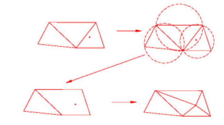
The second family of methods includes approaches based on the initial generation of nodes before connecting them. These are known as Delaunay-Voronoï methods and they are based on the insertion of nodes, one by one, into the mesh with respect (at each step) to the Delaunay criterion.
The last family of methods includes approaches based on the simultaneous generation of nodes and elements. Advancing front methods can be classified in this category. In this case, elements are created, repeatedly, starting from the boundary of the body (3D) or face (2D) to be meshed through the advance of a front inside it. The process stops when the front is empty.

Figure 2 : The insertion of node according to the principle of Delaunay

The advancing front method : the method used in MAGiC
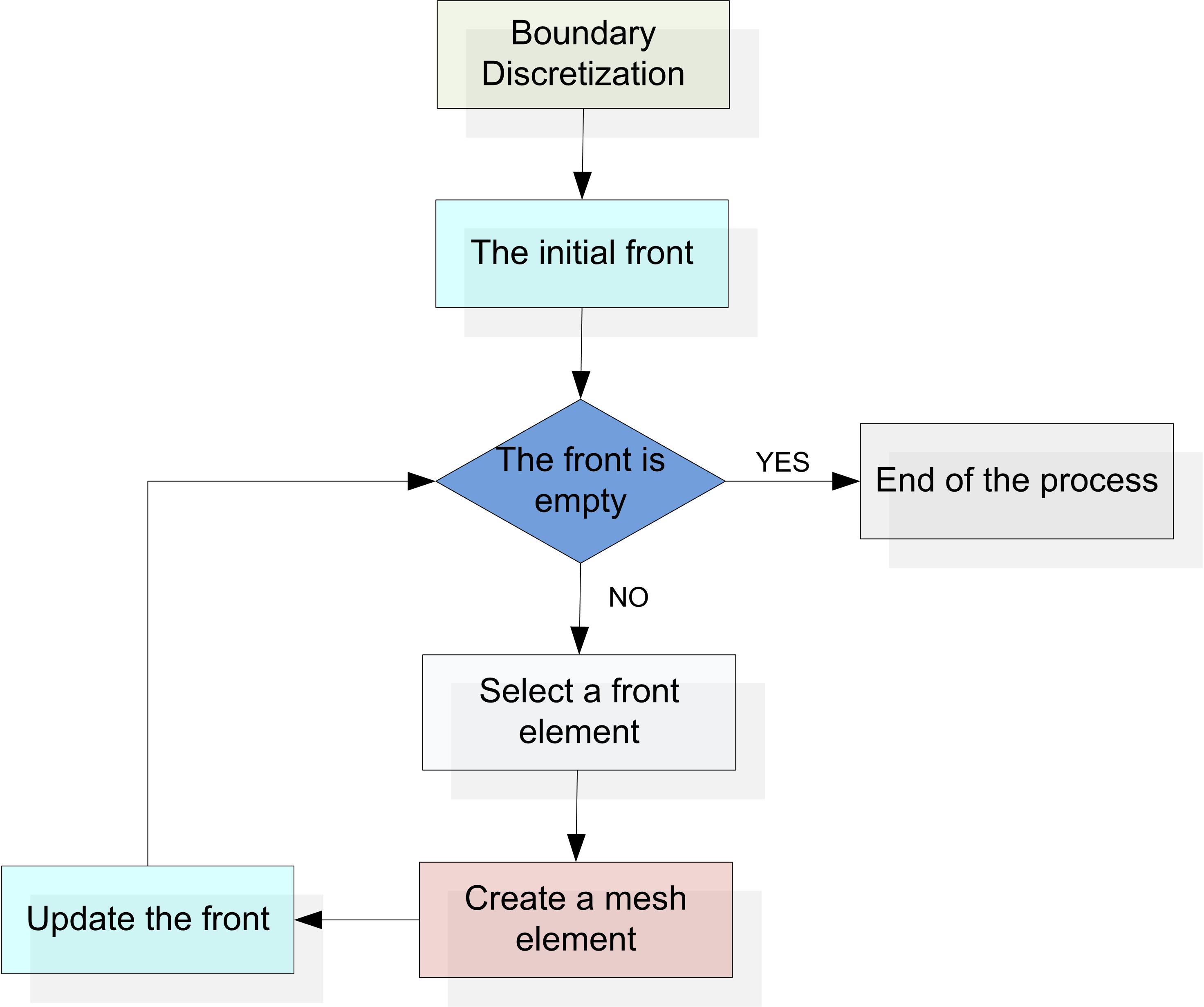
- Initializing the front on the boundary. The front is a set of segments in 2D and triangles in 3D.
- Ordering the front elements (segments or triangles).
- Selecting the first element in the front (candidate element).
- Calculating the position of an ideal node from this element.
- Identifying nodes that are close to this ideal node.
- Classifying the identified nodes
- Creating a valid element using the first node which allows it
- Updating the front
- While the front is not empty return to step 3
- Step 2 is carried out without any theoretical justification. The front elements are sorted following empirical rules that can be very different between two implementations of the method: this is a first empirical dimension of the algorithm.
- Step 4 can be carried out in various ways according to whether emphasis is made on mesh quality or convergence. It is particularly useful to anticipate the meeting of the front with itself in order to increase the chances of convergence. A possible solution is to calculate the ideal node position considering two factors. The first factor, described as local, takes into account the element's shape. The second, described as global, takes into account the possible meeting of the front with itself: this is a second empirical dimension of the algorithm.
- The classification applied at step 6, like for step 2, does not follow any precise mathematical scheme: this is a third empirical dimension of the algorithm.
- Step 7 is crucial. What could be done if no selected node makes it possible to build a valid element? An answer to this question has to be developed in order to solve the problem. The way this is achieved constitutes a fourth empirical dimension in the algorithm. The calculation of whether an element is valid or not is another source of error in the algorithm. In fact, this is achieved by calculating precisely whether the mesh created intersects or not any element of the front.
Despite these problems, the advancing front method shows strong advantages:
- The process is initialized on the boundary: the boundary is necessarily preserved.
- The local modification of a mesh is made possible by destroying elements and then reconstituting a front. The local remeshing of a part of the body is made possible in order to improve quality or in the case of a local change in the geometry of the model
- Anisotropic mesh generation can be achieved directly during the calculation of the ideal node position, using a metric adapted to the anisotropy.

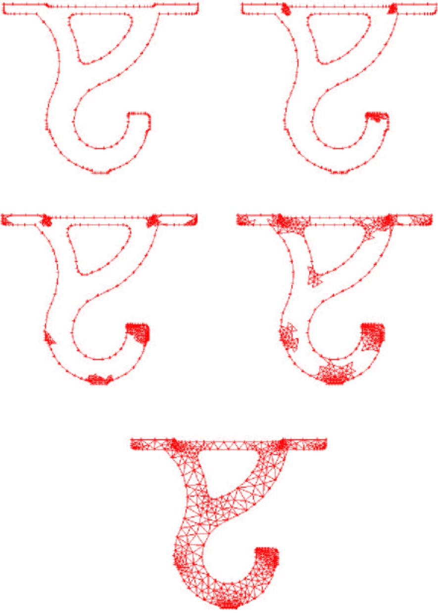
Figure 4 : An 2D example of the advancing front method

Video 1 : An 3D example of the advancing front method : here (download the file)
