Vehicle Modeling and Control
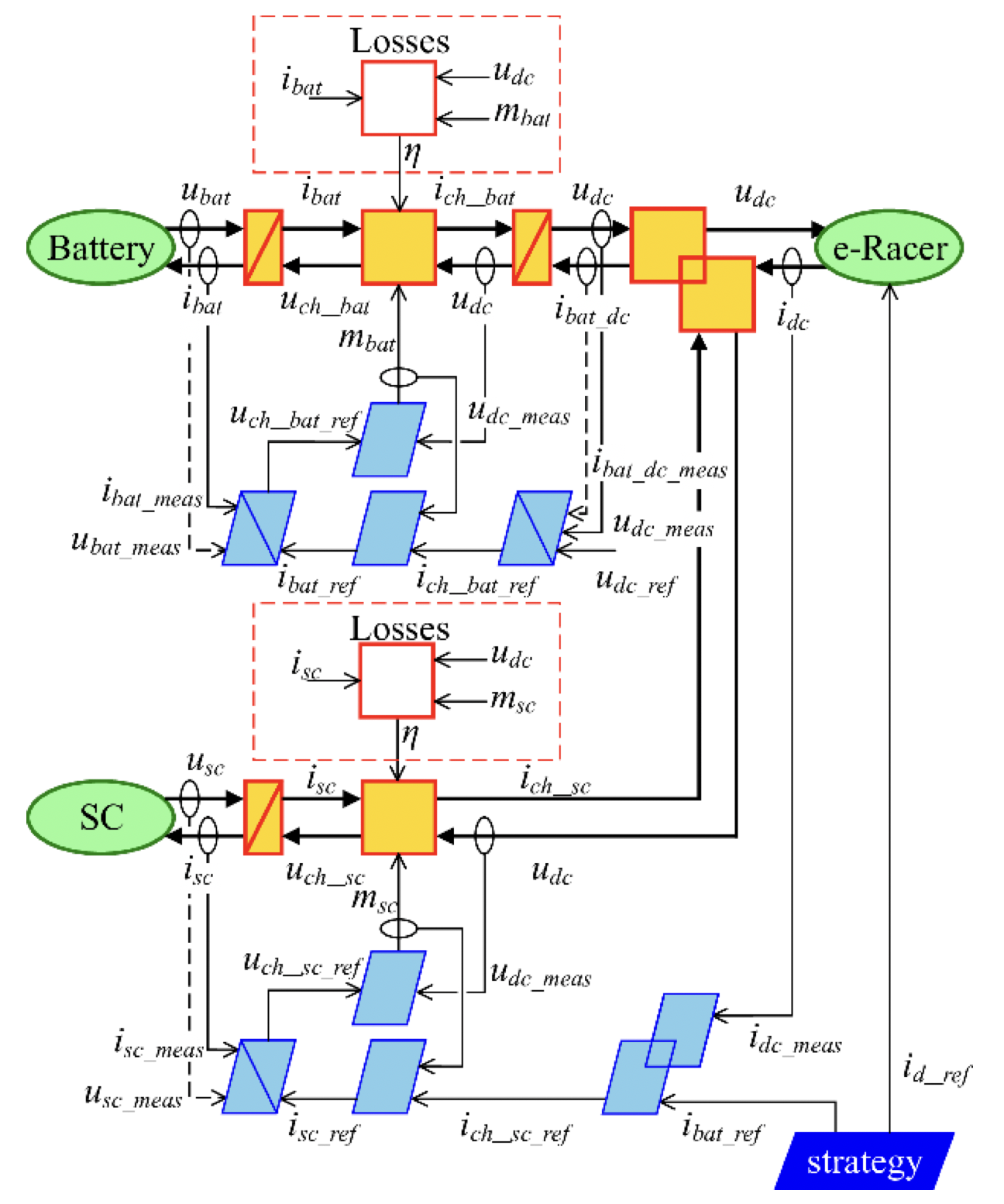
The whole studied vehicle model is implemented in MATLAB/Simulink using the Energetic Macroscopic Representation (EMR), a graphical description to organize dynamical models and to develop control schemes of energetic systems. More details are provided at https://emr-website.univ-lille.fr/
Pictograms are used to describe the system model:
- Green oval pictograms depict the source of the system.
- Orange rectangle pictograms with a diagonal line depict the accumulation element, which stores energy and imposes state variables.
- Orange square and circle pictograms depict mono and multi-domain conversions of energy without accumulation of energy, respectively.
- Overlapping orange pictograms depict coupling elements, which couple power flows without accumulation of energy.
According to the physical causality principle, the accumulation of elements imposes inputs and outputs on other elements. The strength of the EMR is the possibility to deduce an inversion-based control scheme.
Control pictograms are depicted by blue parallelograms:
- Accumulation element is inverted using a closed-loop control;
- Both conversion elements can be inverted using an open-loop control;
- Coupling elements are inverted using a control signal coupling/distribution.
Should note that even if the participants are new to EMR, it will not stop you from proposing your own strategy for this Challenge.
System Representation and Control Scheme of the Studied Vehicle
